Using Inspector
Inspector is the application that can run the models trained in Brain Builder against images captured from industrial or smart cameras and output predictions using industrial protocols.
There are multiple versions of Inspector than can be used depending on the hardware in your environment.
Inspector Versions
- Inspector is a PC application for Windows or Linux environments. It connects to GigE vision standard or USB3 Vision cameras for image inputs and can send outputs via Modbus TCP, Ethernet/IP, or through Neurala's C++ plugin framework. Most of the documentation on this and subsequent pages is specific to this version of Inspector.
- InspectorWeb is a lightweight version of Inspector built to run directly on smart cameras without requiring a separate PC. See documentation for InspectorWeb here: InspectorWeb.
- InspectorLib is a code library that can be used to integrate the functionality of Inspector into other applications and workflows. See documentation for InspectorLib here: InspectorLib.
⚙️ Settings
The first time Inspector is run, the application will walk the user through setup screens for key configuration options. These can be edited later on by clicking the gear icon at the bottom left of Inspector to reach the settings page.
Connect to Brain Builder
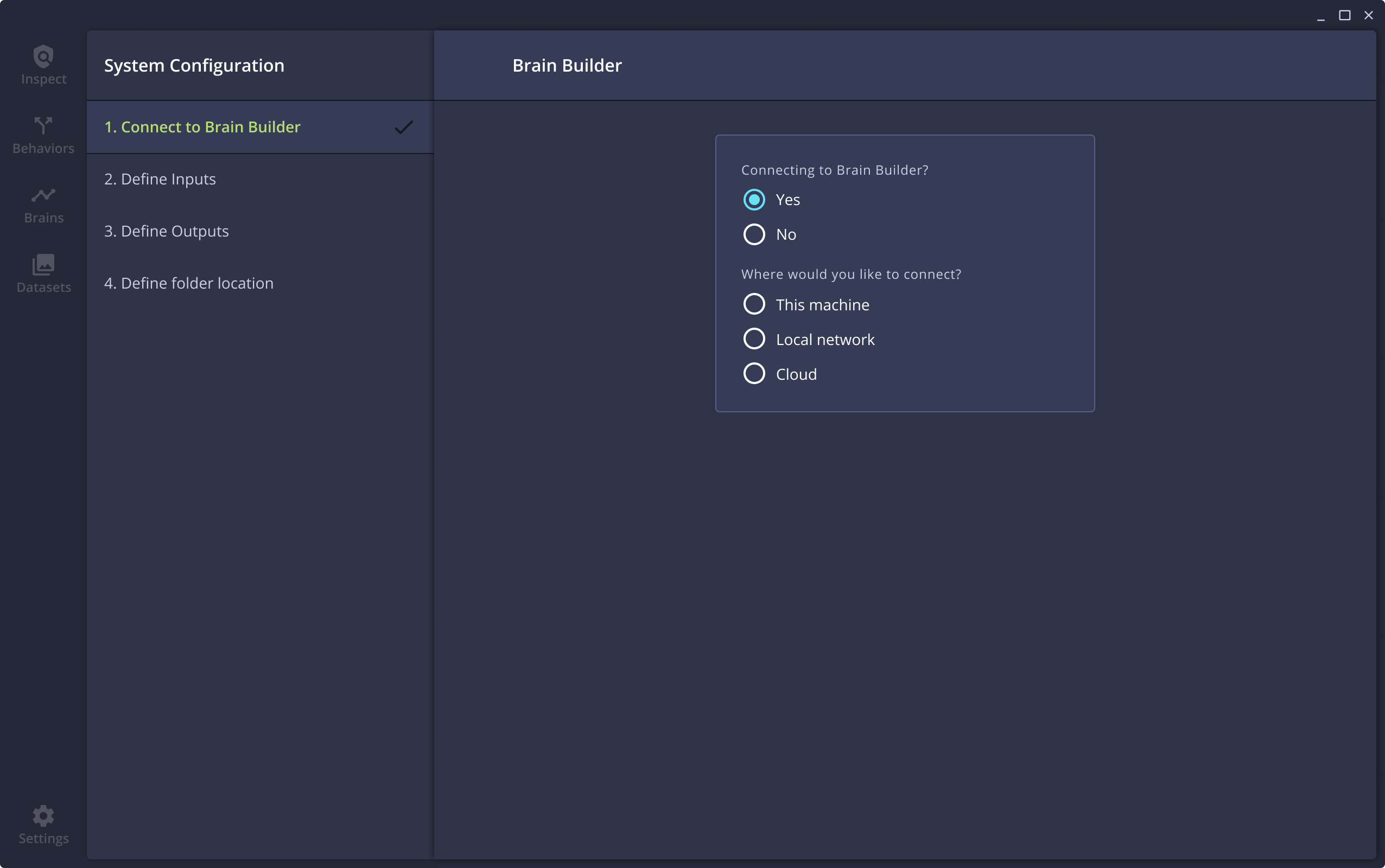
The first configuration step is to connect Inspector to Brain Builder in one of three locations - on this computer, on a local server, or in the cloud.
Depending on your selection, you will be prompted for additional information:
- This machine - enter the user credentials for the instance of Brain Builder that has been installed on this computer. These credentials are created by the user the first time Brain Builder is opened.
- Local network - enter the address of the networked computer where Brain Builder is running and the user credentials.
- Cloud - enter the username and password that are associated with your cloud Brain Builder account.
Inspector will connect to the selected Brain Builder environment, confirm the username and password, and return a Success message when complete.
Define inputs
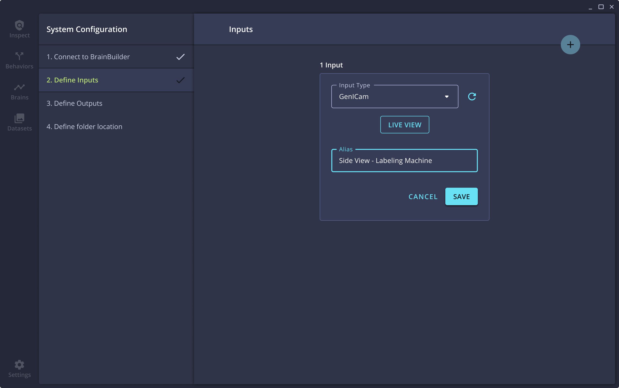
Inputs are the cameras from which Inspector will capture images.
- On the Define Inputs page, click + ADD INPUT to configure the first camera.
Inspector will automatically detect GigE Vision Standard and USB3 Vision cameras that are on the same network as the computer on which Inspector is running. Those cameras will be listed in the drop-down menu called Input Types.
If you installed the Getting Started Project when you installed VIA, you will also see simulated cameras available in this drop-down. - Select the camera you wish to add. To confirm the camera is the correct one, you can click the Live View button to see the image coming in from the camera at that moment.
- Give the camera an Alias (a custom name you can assign to this Input to differentiate it from others).
- Once you have finished configuring the first input, click Save. You can then add additional inputs by clicking the + button at the top-right of the screen.
- When all of your inputs have been successfully defined, click Define Outputs to move to the next configuration step.
Define outputs
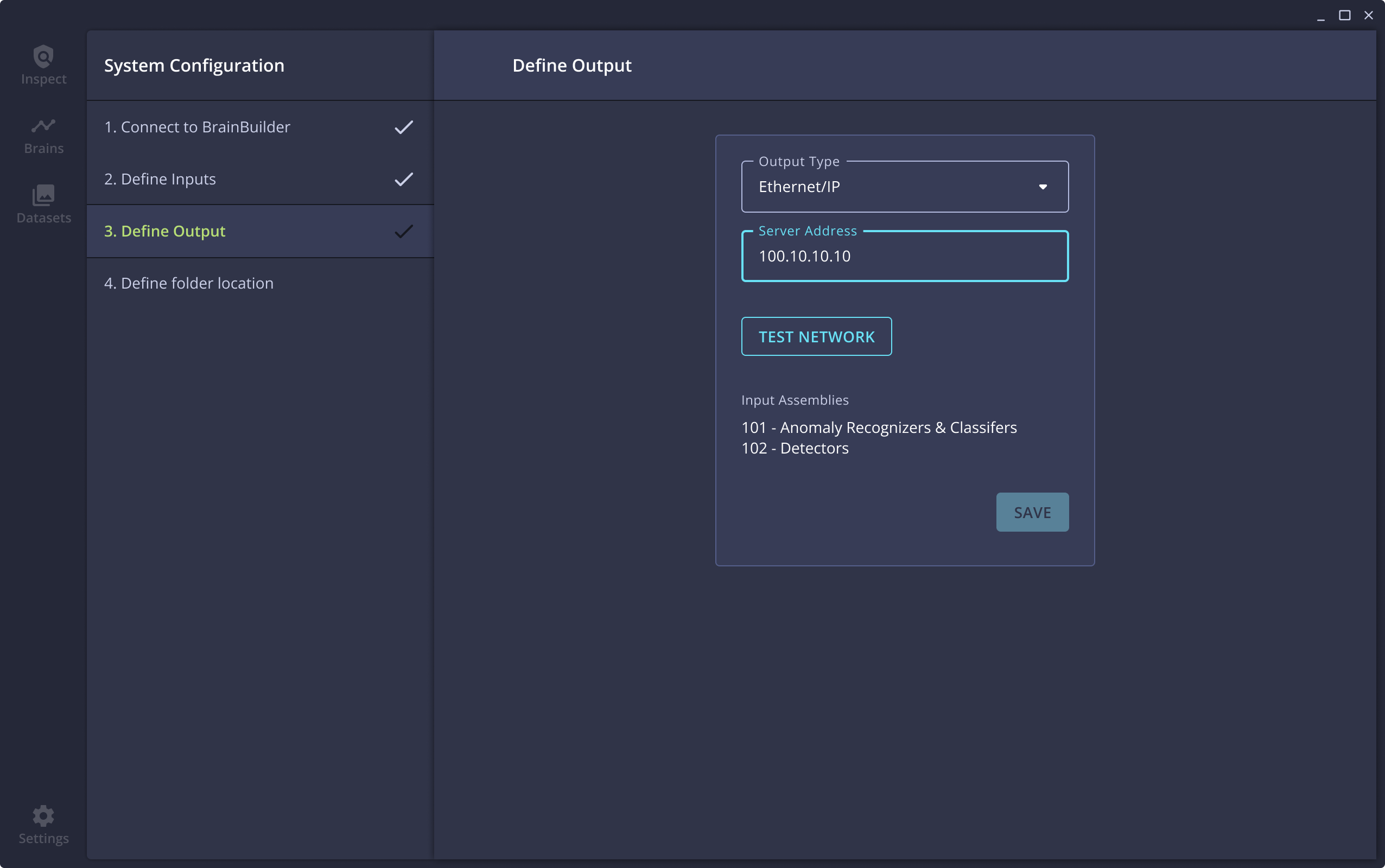
The next configuration step is to define the output protocol that Inspector will use to report results to the manufacturing environment. Inspector supports Modbus TCP, Ethernet/IP, or Neurala's C++ Plugin.
- Select the desired output type from the drop-town menu.
- For Modbus TCP, enter the Server ID of the connected Modbus TCP server. If you do not have a connected Modbus TCP server, any value may be entered to complete the configuration.
- Click Finish Configuration and you are ready to move onto the next step!
Choose data folder location
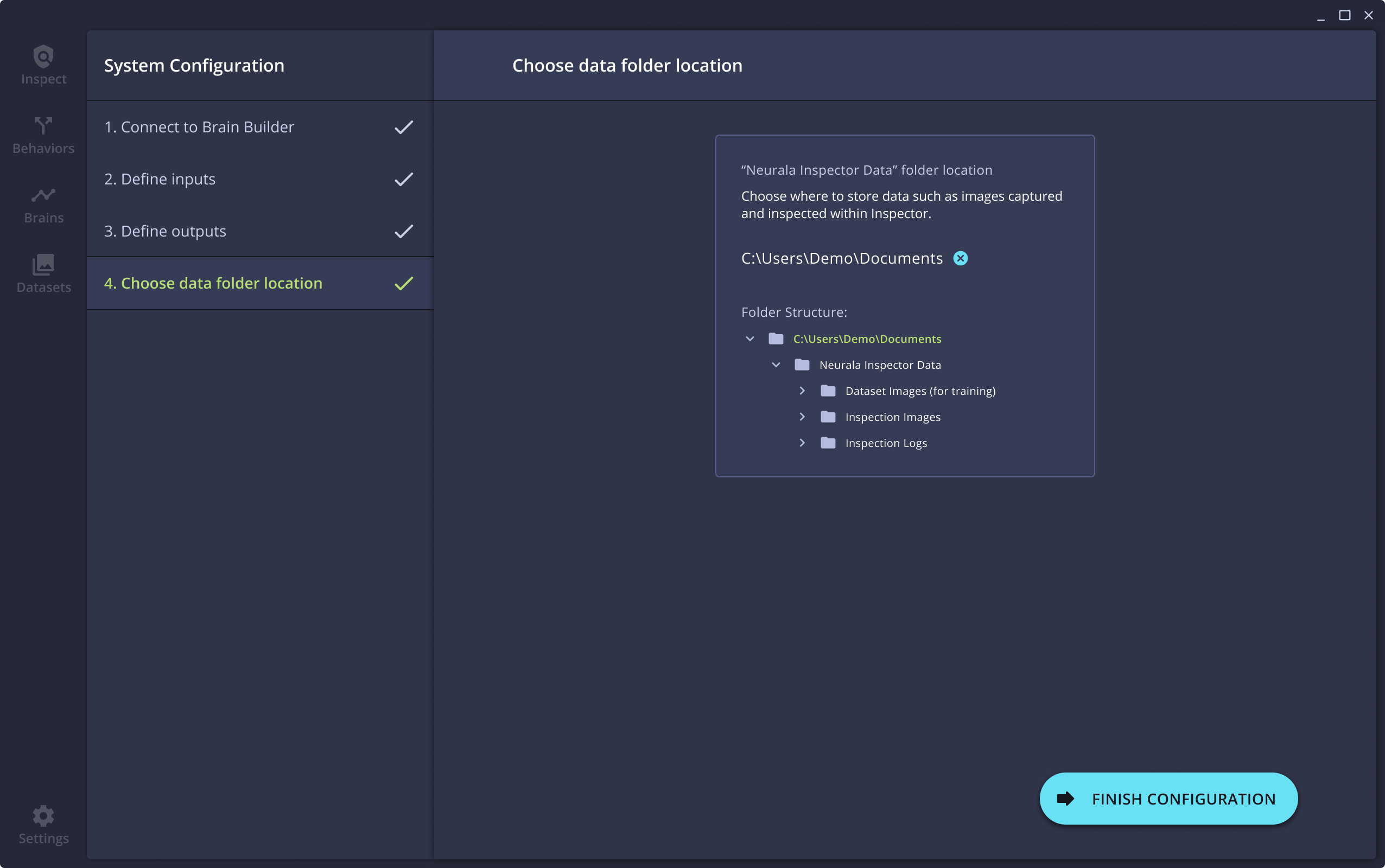
Inspector can capture and save images at multiple points of the training and inspection workflow. Inspector also has options to save inspection logs. By default, these files will be saved into folders in the Documents folder of the computer. This configuration step allows for the selection of an alternate location where those files will be saved.
- The default location is shown. To use this location, click Finish Configuration. To choose an alternative location, click the blue x next to the file path.
- Select the folder for the location where files should be stored.
- Once the new location has been set, click Finish Configuration.
Generate logs
It can be helpful to export log files from Inspector if you need to communicate with Neurala support for assistance resolving a problem.
- Go to the Settings page. Click on About Inspector.
- Click the text that says Generate Logs.
- Select the folder where Inspector should save the log export.
After the process is complete, Inspector will place a zip file with the logs in the selected location.
Modifying Saved Image Settings
In the Inspector configuration screen - on the Settings > About page - there are options to allow the user to change the size and format of the images that are saved during the inspection process. (See Importing Brains for more on enabling image saving during inspections.)
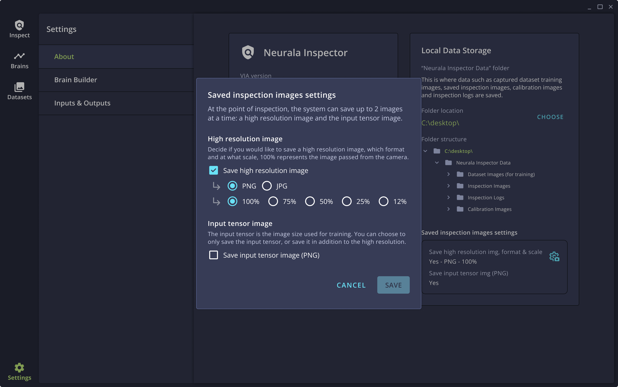
The available configuration options include:
- Save high resolution image - this enables saving a high resolution copy of the image being inspected.
- PNG/JPG allows the user to select the format of the saved image
- 100%/75%/50%/25%/12% allows the user to specify the size, as a percentage of the full image resolution, that should be saved.
- Save input tensor image - this will save a copy of the image that is the same size as the input of the model being used for the inspections. Depending on the model type, this will likely be between 256x256 and 512x512px.
Advanced Camera Configuration
Inspector includes a camera configuration file that can be edited to modify the Genicam configuration parameters that Inspector uses at runtime.
This file can be found at the following location:
- Windows:
- Linux:
This file is originally defined by Pleora eBUS SDK. For more information about .pvcfg files see the Pleora Knowledge Base.
To generate configuration for you own camera, it is recommended to use Pleora eBUS Player (free Windows program). You may have to uninstall VIA before installing eBUS Player, or use another computer to generate your camera configuration. eBUS Player and Neurala Inspector rely on the same eBUS Runtime and cannot be installed
concurrently.
- Once you have configured the camera parameters to your liking, you may save them by
navigating toFile > Save.... Save anywhere convenient. - Next, open the configuration file with a text editor such as Notepad.
- Locate your device configuration (you may find it easiest to search for the device mac address).
- The
<device>tag may be unnamed. Rename using the Renaming Rules mentioned below. - Locate your stream configuration.
- Rename
<stream>using the Renaming Rules mentioned below.
Renaming RulesFor your convenience, we accept the following names for both Stream and Device, in the following order:
- Camera User defined name
- Camera Serial
- Camera Networking ID ID (MAC or USB index)
- Camera Model Name
- Camera Vendor Name
- Interface ID (MAC or USB index)
- Default
The Interface entry may be useful for Stream configuration.
From there, you can copy device and stream blocks to the Default.pvcfg file.
If you want to prevent your changes to be overridden during a future install, copy Default.pvcfg where convenient, and set the environment variable NEURALA_EBUS_PVCFG to point to it. If you had to create this variable, you will have to restart for the changes to take effect.
Updated about 1 year ago